10k Thermistor Chart: Type 2 vs Type 3 vs 3950 Tables
Sep 24, 2026A 10k NTC thermistor reads 10,000 Ω at 25 °C (77 °F), whichever curve it follows. Away from 25 °C the curves separate. At 0 °C a Type 2 thermistor reads 32,651 Ω, a Type 3 reads 29,490 Ω,
a 10k 3950 part reads about 32,755 Ω and a 10k 3435 part about 27,700 Ω.
The chart below gives all four curves from −40 to 125 °C, by the error a controller shows when it expects one curve and gets another.
Reviewed by the Focusens Engineering Team, 24 September 2026.
| °C | °F | Type 2 (10K3A1), Ω | Type 3 (10K4A1), Ω | 10k 3950, Ω | 10k 3435, Ω |
|---|---|---|---|---|---|
| −40 | −40 | 336,098 | 239,828 | 343,633 | 204,700 |
| −30 | −22 | 176,803 | 135,233 | 179,267 | 118,500 |
| −20 | −4 | 97,006 | 78,930 | 97,840 | 71,020 |
| −10 | 14 | 55,304 | 47,549 | 55,595 | 43,670 |
| 0 | 32 | 32,651 | 29,490 | 32,755 | 27,700 |
| 10 | 50 | 19,903 | 18,787 | 19,938 | 18,070 |
| 20 | 68 | 12,493 | 12,268 | 12,501 | 12,110 |
| 25 | 77 | 10,000 | 10,000 | 10,000 | 10,000 |
| 30 | 86 | 8,056 | 8,196 | 8,051 | 8,301 |
| 40 | 104 | 5,325 | 5,594 | 5,315 | 5,811 |
| 50 | 122 | 3,601 | 3,893 | 3,588 | 4,147 |
| 60 | 140 | 2,487 | 2,760 | 2,473 | 3,011 |
| 70 | 158 | 1,752 | 1,990 | 1,738 | 2,224 |
| 80 | 176 | 1,256 | 1,458 | 1,243 | 1,668 |
| 90 | 194 | 916 | 1,084 | 904 | 1,267 |
| 100 | 212 | 678 | 817 | 668 | 975 |
| 110 | 230 | 510 | 624 | 500 | 760 |
| 120 | 248 | 388 | 482 | 380 | 598 |
| 125 | 257 | 341 | 426 | 333 | 533 |
Sources, one per column. Type 2: Measurement Specialties (now TE Connectivity) 10K3A1 datasheet. Type 3: TE Connectivity 10K4A1 datasheet. Both columns agree with Vishay Curve 1 and Curve 9 in the Vishay NTC resistance/temperature conversion tables to within 0.3%, under 0.1 K, from −20 to 100 °C.
10k 3950: typical values from the Zhuhai Hongjiacheng HNTC-103F3950FB datasheet, a B25/50 = 3950 K material, rounded to the ohm. 10k 3435: Semitec 103JT datasheet, B25/85 = 3435 K, rounded to the ohm. Fahrenheit values are converted and rounded to the whole degree.
The 3950 and 3435 columns each come from one manufacturer's material. Other materials sold under the same beta number follow a slightly different curve, because a beta value fixes two points and the rest of the curve depends on the ceramic.
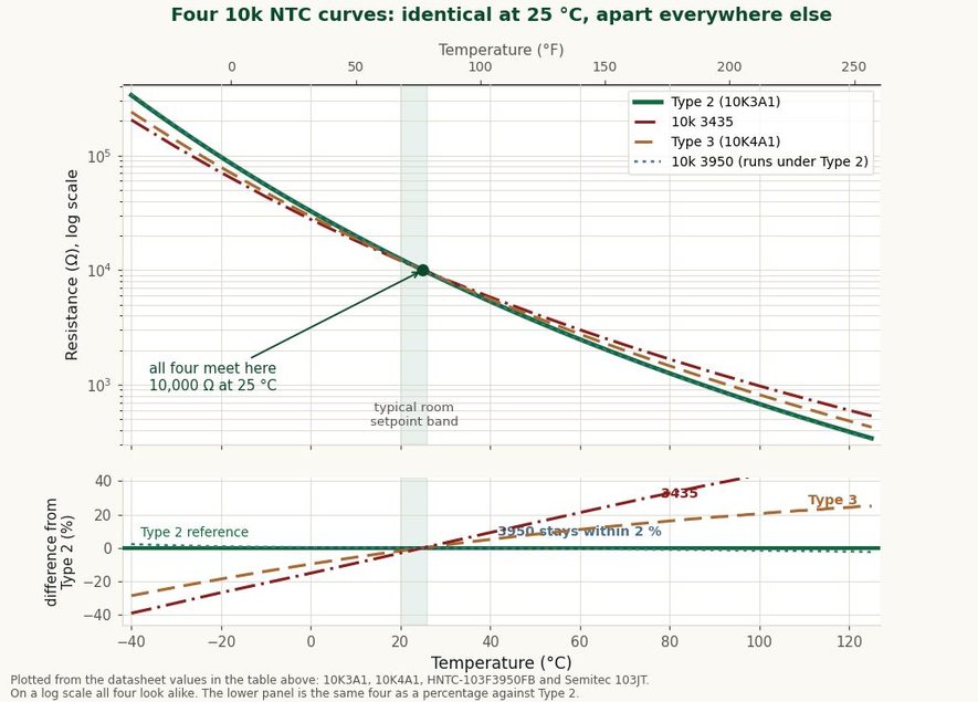
Plotted from the datasheet values in the table above. The lower panel is the same four curves measured against Type 2.
Ask for the part's own resistance table; the beta alone does not define it.
"Type 2" and "Type 3" are building-automation names, not a standard. In many North American HVAC output tables, a table labelled 10K-2 or Type II carries the values of the 10K3A1 curve (Vishay Curve 1), and a table labelled 10K-3 or Type III carries the 10K4A1 curve (Vishay Curve 9).
The beta values below put all four materials on the same footing.
| Common name | Element curve | Published beta | B25/50 | B25/85 | B0/50 |
|---|---|---|---|---|---|
| 10K Type 2 (10K-2, Type II) | 10K3A1, Vishay Curve 1 | B25/85 = 3976 K | 3936 K | 3977 K | 3892 K |
| 10K Type 3 (10K-3, Type III) | 10K4A1, Vishay Curve 9 | B25/85 = 3694 K | 3636 K | 3694 K | 3575 K |
| 10k 3950 | HNTC B25/50 = 3950 K material | B25/50 = 3950 K | 3950 K | 3998 K | 3904 K |
| 10k 3435 | Semitec 103JT | B25/85 = 3435 K | 3392 K | 3435 K | 3353 K |
The three right-hand columns are calculated directly from each datasheet's tabulated resistance at 0, 25, 50 and 85 °C. The calculated B25/85 for Type 2 is 3977 K against the published 3976 K, a rounding difference.
Three details in that table are easy to misread.
The element that HVAC tables call Type 2 is sold as 10K3A1, and the Type 3 element is 10K4A1, so the digit in the part number is not the Type. Controller menus do not agree on the names either.
Schneider Electric's EBO knowledge base states that 10K4A1 is "also referred to as 10K Type 3", yet in the same EBO list the "Type III (Satchwell)" setting uses 10K3A1, the curve most HVAC tables call Type 2, and 10K4A1 appears under "Type I (Continuum)".
Neptronic notes that Type 3 tables can differ slightly between manufacturers. Johnson Controls' TEC2245-4 thermostat bulletin specifies "10k ohm Johnson Controls Type II Negative Temperature Coefficient (NTC) Thermistor Sensors". Match the element curve designation, or the controller's own resistance table, rather than the Type number.
Some datasheets quote B25/50, as the 3950 part above does. Others quote B25/85, as the 10K3A1, 10K4A1 and Semitec datasheets do. The 10k 3950 material is 3950 K at 25/50 and 3998 K at 25/85.
Compared on the wrong basis, a 3950 part looks further from Type 2 than it is, and a 3435 part looks closer to 3950 than it is. Our NTC thermistor guide to B value and resistance curves explains why the same element carries different B values.
On the 25/85 basis the 3950 material in the chart is 3998 K against Type 2's 3977 K. The error table in the next section shows what that means in degrees.
A controller set for the wrong curve reads correctly at 25 °C and drifts away from it: a Type 2 sensor on a Type 3 input reads about 2 K low at 0 °C and about 7 K high at 100 °C.
A controller converts resistance to temperature with the curve it was configured for. If the sensor follows a different curve, the controller still shows a number, and the error grows in both directions from 25 °C.
Displayed temperature minus actual temperature, in kelvin:
| Sensor installed → controller set for | −20 °C | 0 °C | 10 °C | 20 °C | 30 °C | 40 °C | 60 °C | 80 °C | 100 °C |
|---|---|---|---|---|---|---|---|---|---|
| Type 3 → Type 2 | +3.6 | +2.0 | +1.2 | +0.4 | −0.4 | −1.2 | −2.9 | −4.5 | −6.2 |
| Type 2 → Type 3 | −3.9 | −2.2 | −1.3 | −0.4 | +0.4 | +1.3 | +3.1 | +5.0 | +6.9 |
| 3950 → Type 2 | −0.1 | −0.1 | 0.0 | 0.0 | 0.0 | 0.0 | +0.2 | +0.3 | +0.5 |
| 3950 → Type 3 | −4.1 | −2.2 | −1.4 | −0.5 | +0.5 | +1.4 | +3.3 | +5.3 | +7.5 |
| 3435 → Type 2 | +5.5 | +3.3 | +2.0 | +0.7 | −0.7 | −2.2 | −5.2 | −8.6 | −12.0 |
| 3435 → Type 3 | +2.0 | +1.4 | +0.9 | +0.3 | −0.3 | −1.0 | −2.6 | −4.4 | −6.3 |
Computed by taking the installed sensor's tabulated resistance at each actual temperature and converting it back through the controller curve's 1 °C datasheet table, interpolating ln R against 1/T.
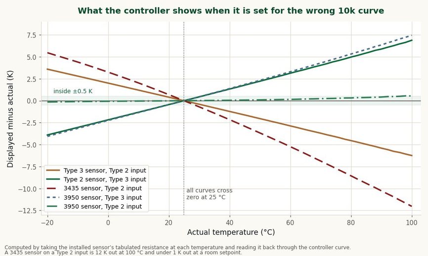
Every mismatch reads correctly at 25 °C. The error grows in both directions from there.
The same comparison at common HVAC temperatures, in °F:
| Sensor → controller | 40 °F | 55 °F | 65 °F | 72 °F | 78 °F | 90 °F |
|---|---|---|---|---|---|---|
| Type 3 → Type 2 | +3.0 | +1.8 | +1.0 | +0.4 | −0.1 | −1.1 |
| Type 2 → Type 3 | −3.2 | −1.9 | −1.1 | −0.4 | +0.1 | +1.1 |
| 3950 → Type 3 | −3.3 | −2.0 | −1.1 | −0.5 | +0.1 | +1.2 |
| 3435 → Type 2 | +4.9 | +3.0 | +1.7 | +0.7 | −0.1 | −1.8 |
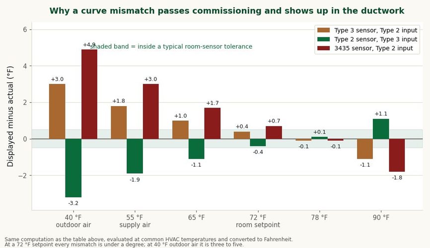
The same comparison at the temperatures a building actually runs at.
A mismatched sensor usually survives commissioning because of the middle columns. At a 72 °F room setpoint a Type 2 sensor on a Type 3 input is off by less than half a degree Fahrenheit, which is inside a typical room-sensor tolerance.
Neptronic, a controller maker, makes the same point in the note linked above: between 15 and 30 °C the curves barely differ, and they diverge away from 25 °C. The same sensor in a 55 °F supply-air duct reads about 2 °F low,
and on a 180 °F hot-water loop it reads about 9 °F high.
If a building's zone sensors look fine but its discharge air, outdoor air or hot-water readings are off in a consistent direction, check the curve setting before replacing sensors. For how these sensors sit in an air-conditioning system, see how air conditioning indoor temperature sensors work.
Read through a Type 2 curve, the 10k 3950 material in the chart is within 0.1 K from −10 to 40 °C, 0.15 K at −20 and 60 °C, and 0.5 K at 100 °C.
Read through a Type 3 curve, the same part is off by as much as a genuine Type 2 sensor would be.
That makes a 10k 3950 NTC a reasonable candidate where a Type 2 sensor is specified, the working range stays within 0 to 60 °C, and the specified accuracy is ±0.5 K or looser.
It is the wrong part where Type 3 is specified. Three conditions apply. The result holds for the 3950 material tabulated here, so confirm it against the actual supplier's table at your working temperatures.
A part with ±1% tolerance on R25 is already about ±0.23 K at 25 °C before any curve difference, so it cannot meet a ±0.2 °C interchangeable Type 2 grade. And a building specification that names a curve by manufacturer designation takes precedence over any numerical closeness.
A reading at 25 °C cannot separate the curves, because all of them read 10 kΩ there. Two readings away from 25 °C can.
| Reading in an ice-water bath (0 °C) | Reading in 60 °C water | Curve |
|---|---|---|
| about 32,650 Ω | about 2,490 Ω | Type 2, or a 3950 material close to it |
| about 29,490 Ω | about 2,760 Ω | Type 3 |
| about 27,700 Ω | about 3,010 Ω | a 3435 material |
Use a well-stirred bath of crushed ice and water for the 0 °C point and a reference thermometer for the warm point. Give the sensor several minutes to settle, then disconnect it from the controller and measure at its leads, so cable resistance and input circuitry stay out of the reading.
Type 3 and 3435 separate clearly from Type 2 at 0 °C: 29,490 Ω and 27,700 Ω against 32,651 Ω is a 10% to 15% difference, far larger than a ±1% tolerance.
Type 2 and the 3950 material differ by about 0.3% at 0 °C and cannot be told apart this way. For the HVAC range they do not need to be. Meter setup and lead handling are covered in our guide to testing an NTC thermistor with a multimeter;
use the tabulated values above, rather than a beta-equation estimate, to identify a curve.
A 10k thermistor datasheet usually states two tolerances: one on the resistance at 25 °C and one on the beta value. They matter at different temperatures.
| Actual temperature | ±1% on R25 | ±1% on beta | Both at their limit |
|---|---|---|---|
| −20 °C | ±0.17 K | ±0.39 K | ±0.56 K |
| 0 °C | ±0.20 K | ±0.23 K | ±0.43 K |
| 25 °C | ±0.23 K | 0 | ±0.23 K |
| 60 °C | ±0.28 K | ±0.39 K | ±0.66 K |
| 100 °C | ±0.34 K | ±0.92 K | ±1.26 K |
Computed for the Type 2 curve from its sensitivity at each temperature: −4.39 %/K at 25 °C and −2.94 %/K at 100 °C.
The R25 tolerance sets the error near room temperature. The beta tolerance sets it at the ends of the range and is zero at 25 °C by definition. A part specified at ±1% on R25 and ±1% on beta is therefore about ±0.2 K at a 25 °C setpoint and about ±1.3 K at 100 °C.
Interchangeable elements such as the 10K3A1 are specified differently, as a tolerance in °C over 0 to 70 °C, with ±0.5% on beta. For a controller that works mainly at one temperature, ask the supplier for the tolerance at that temperature rather than at 25 °C.
For firmware, the Steinhart-Hart equation 1/T = A + B·ln(R) + C·(ln R)³, with T in kelvin, reproduces each curve closely.
| Curve | A | B | C | Largest error, −40 to 125 °C |
|---|---|---|---|---|
| Type 2 (10K3A1) | 1.129032 × 10⁻³ | 2.341421 × 10⁻⁴ | 8.762059 × 10⁻⁸ | 0.05 K |
| Type 3 (10K4A1) | 1.028419 × 10⁻³ | 2.392462 × 10⁻⁴ | 1.562178 × 10⁻⁷ | 0.04 K |
| 10k 3950 (HNTC) | 1.142941 × 10⁻³ | 2.325551 × 10⁻⁴ | 8.858792 × 10⁻⁸ | 0.14 K |
| 10k 3435 (Semitec 103JT) | 8.262643 × 10⁻⁴ | 2.629842 × 10⁻⁴ | 1.345655 × 10⁻⁷ | 0.13 K |
Least-squares fits to the datasheet tables linked under the chart: every 1 °C for Type 2, Type 3 and 3950, and, for 3435, the 20 tabulated points from −40 to 125 °C (10 °C steps plus 25, 85 and 125 °C).
Our catalogue lists 10k NTC elements at two of the beta values charted above and a third that matches the Type 2 beta. The MF52 epoxy NTC thermistor series is catalogued with B25/50 options from 3100 to 4500 K,
including 3950 K at R25 from 5 to 100 kΩ, with ±1% beta tolerance.
The MF58 glass NTC thermistor includes 3950 K at R25 from 10 to 50 kΩ, with beta tolerance down to ±0.5%. Our MFT NTC probes use 10k at B25/85 = 3435 K as the standard value, with other R-T curves available.
Our FHR medical probes offer a 10k option at B25/85 = 3976 K, the published beta of the 10K3A1 curve.
A matching beta is a starting point, not a curve match. With a Type 2 or Type 3 replacement enquiry, include the curve designation or the controller's resistance table so the part can be checked against that table at your working temperatures.
Probes for building services are under sensors for HVAC, and other housings are under NTC thermistor sensors and probes. For the physics behind the curves, see our overview of negative temperature coefficient thermistors,
and for the usable range of a 10k NTC, see the temperature range of the NTC 10k.
10K Type 2 and Type 3 thermistors both read 10,000 Ω at 25 °C. Type 2 (10K3A1, B25/85 = 3976 K) is the steeper curve: 32,651 Ω at 0 °C and 678 Ω at 100 °C.
Type 3 (10K4A1, B25/85 = 3694 K) reads 29,490 Ω at 0 °C and 817 Ω at 100 °C. Swapped between controllers, the two curves disagree by about 2 K at 0 °C and 6 to 7 K at 100 °C.
A 10K NTC thermistor reads 10,000 Ω at 25 °C. For the four curves on this page, it reads 27.7 to 32.8 kΩ at 0 °C and 668 to 975 Ω at 100 °C. Use the chart above for the curve your part follows.
A 10K Type 3 thermistor is a 10 kΩ at 25 °C NTC thermistor that follows the 10K4A1 curve, Vishay Curve 9, with B25/85 = 3694 K. Some controller menus use a different Type number for this curve, so check the controller's own table.
A 10k 3950 thermistor is not the same as Type 2 by specification, but it is close in practice. The 3950 material in the chart reads within 0.1 K of Type 2 from −10 to 40 °C and about 0.5 K off at 100 °C. It is not a substitute for Type 3.
A Type 3 sensor on a Type 2 input reads correctly near 25 °C and drifts away from it: about 2 K high at 0 °C and about 4.5 K low at 80 °C. Change the input setting to Type 3 or fit a Type 2 sensor.
No.1 XiSan Road, Electromechanical Industry Park , High&New Tech.Zone. Hefei,Anhui,China
โทร : +86-551-69109668
Whatsapp : +86-13339100504
อีเมล : info@focusens.com
Skype : melodyliu520






 +86-551-69109668