How to Choose the Right Wall Mount Room Temperature Sensor for BAS Systems
Apr 03, 2026Choosing a wall mount room temperature sensor for a building automation system (BAS) requires evaluating six core parameters: sensing element type (NTC thermistor, RTD PT100/PT1000, or digital), output signal format (passive resistance, 4-20mA, or 0-10V), accuracy class (±0.3°C for critical zones vs ±0.5–1°C for general HVAC), enclosure and utility box compatibility, BAS protocol integration (BACnet, Modbus), and long-term calibration stability. For engineers sourcing sensors at scale, the decision between a passive thermistor sensor and an active smart temperature transmitter is not about cost — it is about where signal conditioning responsibility sits in your system architecture.
Here is the uncomfortable truth that 15 years of manufacturing temperature sensors for engineers across more than 60 countries has taught us:
Most online selection guides for wall mount room temperature sensors are written backwards.
They start with product features — housing material, IP rating, color — and work outward toward the application. The result is engineers who specify the wrong sensing element for their BAS controller input, choose passive thermistor sensors when their wiring runs exceed 30 meters, or select transmitters with 0-10V output for a controller that expects 4-20mA — and then discover the mismatch during commissioning.
The correct approach is the opposite. Start with your building automation system's input architecture, work through your environmental conditions and accuracy requirements, and arrive at the sensing element and output format as outputs of the decision process — not starting assumptions.
This guide structures the selection process exactly that way. It is written for mechanical and electrical engineers who are at the research stage of a BAS sensor specification and need a technically rigorous, vendor-agnostic framework before evaluating specific products.
Before selecting any sensor, you must be precise about what role it plays in the control loop.
In a modern building automation system, the wall mount room temperature sensor is the primary feedback input for zone-level HVAC control. It is not simply measuring temperature — it is providing the real-time process variable (PV) that the BAS controller compares against the zone setpoint (SP) to compute a control output that drives actuators: VAV dampers, fan-coil unit valves, electric heaters, or chilled beam outputs.
This means the sensor's performance characteristics directly determine the stability, accuracy, and energy efficiency of the entire zone control loop. A sensor with ±1.0°C accuracy in a zone setpoint of 22°C means the control system is effectively flying blind across a 2°C band — which translates directly into comfort complaints and unnecessary HVAC cycling.
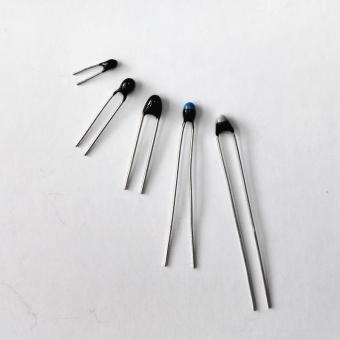
Temperature sensors used in the building automation industry are typically nothing more than temperature-controlled resistors, or thermistors. The resistance of the device is inversely proportional to the temperature being sensed: as the temperature rises, the resistance of the thermistor drops. Today's thermistors offer tight tolerance and good stability and repeatability at a relatively low cost, making them extremely applicable to the HVAC industry.
However, thermistors are only one of three sensing element families available to BAS engineers — and choosing among them is the first and most consequential decision in the selection process.
| Family | What it does best | Where it fails | Best-fit application |
|---|---|---|---|
| NTC thermistor | Low cost, good tolerance to moderate wiring runs | Nonlinear curve, B-value dependency | Commercial HVAC room sensing |
| RTD (PT100 / PT1000) | Linearity and stability | PT100 sensitive to lead resistance | Critical zones, longer wiring, European specs |
| Active smart transmitter | Linear output, no lookup table, no lead compensation | Requires power and has higher unit cost | Large BAS projects, noisy environments, long cable runs |
NTC thermistors are the dominant sensing element in commercial HVAC room temperature sensing. Their resistance decreases predictably as temperature increases. The most common configurations in BAS applications are 10kΩ at 25°C (Type II and Type III per ASHRAE 135/NTC standard curves), though 20kΩ and 100kΩ variants exist for specific applications.
Where they excel:
The high resistance of a 10kΩ NTC thermistor means that lead wire resistance — which typically ranges from 5Ω to 20Ω in commercial installations — represents less than 0.2% of the total circuit resistance at room temperature. This makes NTC thermistors inherently tolerant of moderate wiring runs without requiring compensation circuitry.
Where engineers get burned:
The thermistor's resistance-temperature relationship is nonlinear. The Steinhart-Hart equation describes this relationship mathematically, and every BAS controller that accepts a passive thermistor input has this curve baked into its lookup table firmware — for a specific thermistor characteristic (B-value). If you install a thermistor with a B25/85 value of 3950 into a controller programmed for a B25/85 of 3435 (a common Siemens/Johnson Controls curve), you will have a systematic error of up to ±2°C across the sensing range. This is the single most common commissioning error in BAS sensor installations — and it is entirely preventable through proper specification.
The contrarian take on NTC for BAS:
Most engineers default to passive NTC thermistor sensors because they are inexpensive and simple. But the total installed cost calculation changes significantly when you account for controller input card costs (each analog input has a real cost), calibration labor, and the cost of systematic errors from B-value mismatches. For large projects with more than 50 sensing points, the economics of active transmitters often justify their unit price premium.
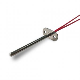
RTD sensors use the predictable linear increase in platinum wire resistance with temperature, standardized to IEC 60751. PT100 has a nominal resistance of 100Ω at 0°C; PT1000 has 1000Ω at 0°C.
Where PT1000 wins over PT100 in BAS:
PT100's 100Ω base resistance makes it vulnerable to lead wire resistance errors in long-distance wiring. A 50-meter cable run using 0.5mm² copper wire adds approximately 3.5Ω per conductor — which represents a 3.5% error on a PT100 but only a 0.35% error on a PT1000. For VAV and fan-powered box applications where wiring runs can be substantial, probe sensor selection must account for the electrical characteristics of the installation, not just the sensing element accuracy.
This is why in European BAS specifications, PT1000 dominates as the passive RTD standard, while North American specifications more frequently specify thermistors or active 4-20mA transmitters.
The accuracy advantage:
Class A PT1000 sensors achieve ±0.15°C accuracy at 0°C per IEC 60751 — significantly better than typical NTC thermistor interchangeability of ±0.2–0.5°C. For critical environments like operating theatres, pharmaceutical cold storage, or data center cooling, RTD sensing elements justify their additional cost.
This is where the majority of modern BAS sensor specifications are migrating — and where Focusensing's core product offering sits.
An active smart temperature transmitter integrates the sensing element (typically an NTC thermistor or digital sensing IC), signal conditioning circuitry, linearization, and a standardized output signal (4-20mA or 0-10V) into a single wall-mount enclosure. The controller receives a clean, linear analog signal that requires no lookup tables, no lead resistance compensation, and no B-value matching.
For BAS applications, space thermostats may provide thermistor or 4-20mA output RTD signals. The accuracy of a transmitter shall be unaffected by wiring distances up to 700 feet (approximately 213 meters). This is the defining practical advantage of active transmitters over passive sensors in large commercial buildings.
For product ① in the Focusensing lineup: Our FHT20 Series Wall Mount Temperature Humidity Transmitter represents precisely this active transmitter architecture — combining both temperature and humidity sensing in a single wall-mount enclosure, with Sensirion SHT21 sensor element, ±3%RH humidity accuracy, and selectable 4-20mA or 0-10V output — specifically engineered for HVAC BAS integration. Calibration data and linearization are stored on-probe, eliminating controller-side compensation requirements.
The output signal format is the specification that most directly determines system compatibility and installation cost. There are four formats you will encounter in BAS temperature sensing:
| Format | Infrastructure requirement | Main strength | Main limitation |
|---|---|---|---|
| Passive resistance | No power supply to sensor; only signal pair | Simple, low wiring burden | Cable-length and EMI sensitivity |
| 4-20mA current loop | Power supply required (typically 12–36VDC) | Noise immunity and diagnostic live zero | Needs powered transmitter |
| 0-10V voltage output | Power supply required | Easy controller interface | More susceptible to cable losses and EMI |
| Digital output | RS485 / Modbus / BACnet MS/TP / 1-Wire | Networked multi-node efficiency | Addressing and bus commissioning complexity |
The sensor itself has no power supply. The BAS controller sources a small excitation current through the sensing element and measures the resulting voltage to calculate resistance, then converts to temperature via its internal lookup table or Steinhart-Hart calculation.
Infrastructure requirements: No power wiring to the sensor — only a signal pair (2-wire for thermistor; 2-, 3-, or 4-wire for RTD).
Key limitation: Signal quality degrades with cable length and is susceptible to electromagnetic interference in electrically noisy environments (near VFDs, large motors, or fluorescent lighting ballasts).
The most robust signal format for long-distance BAS wiring. Current loops are inherently immune to resistive cable losses — a 4mA signal is 4mA whether the cable is 5 meters or 500 meters (within practical power supply limits). The transmitter requires a power supply (typically 12–36VDC) but delivers a noise-immune, loop-powered signal to any standard analog input card.
Why 4-20mA is the correct default for most commercial BAS applications:
A 4mA live zero allows the controller to detect open-circuit or failed sensor conditions — the signal drops below 4mA. A passive resistance sensor cannot provide this diagnostic. In a building with 200+ sensing points, the ability to automatically flag failed sensors rather than relying on manual rounds is operationally significant.
The Focusensing FHT20 transmitter supports both 2-wire 4-20mA and 3-wire 4-20mA connection modes, with an ordering guide that specifies the output configuration at time of order. This eliminates field-level ambiguity during commissioning.
Voltage output transmitters are simpler to wire (the controller input directly reads voltage without a burden resistor) but are more susceptible to cable losses over long distances and EMI pickup. Best suited for installations where cable runs are under 30 meters and EMI exposure is low.
Digital sensing is the emerging format for smart building applications where sensors communicate directly on a fieldbus network rather than terminating at analog input cards. The advantage: a single RS485 bus can support 32 or more sensor nodes, dramatically reducing cabling cost in multi-zone buildings.
The honest trade-off: Digital protocols require address configuration (each sensor on the bus needs a unique node address), bus termination, and more sophisticated commissioning. For large-scale BAS retrofit projects, the cabling cost savings often outweigh the commissioning overhead. For simple zonal HVAC control in smaller buildings, analog 4-20mA remains the lower total installed cost option.
The accuracy specification on a sensor datasheet is typically stated at 25°C (reference temperature). Real-world accuracy across the full operating range is always worse — and for BAS applications, the relevant question is accuracy at the actual operating temperature of the space, not the lab reference condition.
| Tier | Application | Required accuracy | Recommended sensor type |
|---|---|---|---|
| Tier 1 | Critical control zones | ±0.2°C to ±0.3°C | Class A PT1000 or premium digital sensing ICs |
| Tier 2 | Commercial comfort HVAC | ±0.5°C | NTC thermistor sensors or active transmitters |
| Tier 3 | General building monitoring | ±1.0°C | Standard NTC thermistors |
Operating theatres, pharmaceutical production, cleanrooms, museum conservation areas, server room precision cooling. These applications require Class A PT1000 RTD sensing elements or premium digital sensing ICs (SHT40, TMP117) with individual calibration certificates.
Open-plan offices, retail spaces, hotel guestrooms, classrooms, commercial kitchens (for ambient, not food temperature). This is the sweet spot where NTC thermistor sensors with tight interchangeability tolerances (Type II or Type III curves) or active transmitters with digitally calibrated sensing elements (SHT21, SHT31) perform excellently at competitive cost. The Focusensing FHT20 Series with Sensirion SHT21 element delivers within this accuracy band across its full operating range.
Stairwells, plant rooms, loading docks, car parks, warehouses. Standard NTC thermistors without premium interchangeability specification are fully adequate.
The contrarian insight: Specifying Tier 1 accuracy across an entire office building because "more accuracy is always better" is a budget waste. But specifying Tier 3 sensors in a comfort zone because they pass price comparison is a guarantee of occupant complaints and energy waste from hunting control loops.
Traditional BAS sensors often fall short, offering limited accuracy, drifting over time, and relying on slow or noisy signals that disrupt stable HVAC control. These shortcomings not only waste energy but also lead to comfort complaints and higher maintenance costs.
The "utility box" aspect of wall mount room temperature sensor specification is where engineering drawings and field reality diverge most sharply — particularly in retrofit projects.
| Mounting type | Typical region | Key risk | What to verify |
|---|---|---|---|
| Single-gang electrical box | North America | Wall damage coverage | Back housing or cover plate dimensions |
| 86mm × 86mm / 120mm × 120mm wall plate | Europe | Visible gaps and aesthetics | Plate size and adaptor compatibility |
| Surface-mount (no box) | New construction | Lower mechanical protection | Cable entry and wall sealing |
The most common mounting standard in North American commercial construction. The sensor's back housing or cover plate must be sized to fully cover the single-gang box cutout and any surface damage around it. In a retrofit scenario where an old thermostat is being replaced by a sensor, the wall damage perimeter around the existing box is often the actual constraint on sensor body dimensions.
Key specification question: Does the sensor have an integral backplate that covers standard single-gang box dimensions, or does it require a separate adaptor plate?
European commercial projects commonly use larger format wall plates. Sensors specified to North American dimensions will have visible gaps around the wall box — aesthetically unacceptable in premium commercial spaces.
Some BAS sensor designs mount directly to a flat wall surface without a back box, with cable entry through the wall surface. These are faster to install in new construction where conduit runs are not yet boxed, but offer less mechanical protection for the wiring terminations.
Space temperature sensors are offered in a vast variety of styles. Most of these are available as vertical mount, meaning that the long dimension of the device is up and down, just like a single-gang light switch. There are, however, adaptor plates or goof plates available for retrofit scenarios to cover a hole left from a horizontal mount thermostat.
The installation location rule that most engineers underweight:
The sensor must be mounted on an interior wall, at a height of 1.2 to 1.5 meters from finished floor level, away from direct solar radiation through windows, away from supply air diffusers, and away from external walls with significant thermal mass effects. A technically perfect sensor installed in a thermally compromised location will consistently produce erroneous readings regardless of its specification.
Outside air wall-mounted sensors shall be provided with a sun shield. Accuracy of the transmitter shall be unaffected by wiring distances up to 700 feet. The sun shield requirement for outdoor sensors applies equally to any indoor sensor positioned near south-facing glazed walls in summer conditions.
Here is a specification decision where standard HVAC practice and optimal BAS performance diverge:
Standard practice: Specify separate temperature sensors and humidity sensors at different points on the HVAC loop — room temperature sensor on the wall, duct humidity sensor in the return air duct.
In advanced BAS systems, combined temperature and humidity sensing provides better control performance. Wall-mounted temperature & humidity transmitters are commonly used for zone-level monitoring.
Optimal practice for energy efficiency: A combined temperature + humidity transmitter at the zone level enables the BAS controller to compute real-time dew point, enthalpy, and comfort index (PMV/PPD per ISO 7730) — enabling demand-controlled HVAC that responds to both thermal and humidity comfort drivers simultaneously.
The energy savings from humidity-informed HVAC control are documented: in climates with humid summers (Southeast Asia, Middle East, Southern US, Mediterranean Europe), reducing relative humidity from 65% RH to 50% RH at a constant 24°C allows the occupied setpoint to be raised by 2–3°C without occupant discomfort — directly reducing cooling energy consumption.
For zone-level combined sensing, the Focusensing FHT20 Series provides both temperature and relative humidity outputs from a single wall-mount enclosure, using the Sensirion SHT21 sensing element — a digitally calibrated capacitive humidity sensor with NIST-traceable calibration data stored on-chip. This eliminates the need to run separate sensor cables to two wall boxes and maintain two BAS point lists per zone, reducing both installation cost and long-term maintenance complexity.
For duct-level monitoring as part of the same HVAC loop, the Focusensing FHT31 Series Duct Temperature Humidity Transmitter mirrors the FHT20's performance specification in a duct-insertion housing. Together, FHT20 (room) and FHT31 (duct) create a paired sensing architecture for complete zone characterization — room comfort conditions versus supply air conditions — enabling supply air reset strategies that are now standard in ASHRAE 90.1 energy code compliance.
| Scenario | Need humidity sensing? | Why |
|---|---|---|
| Humid climate comfort zones | Yes | Controls latent load and comfort |
| Energy-optimized BAS | Yes | Enables dew point and enthalpy logic |
| Dry, general monitoring zones | Optional | Temperature alone may be sufficient |
| Duct-level HVAC optimization | Yes | Supports supply air reset strategies |
Based on the frameworks above, here is a practical specification checklist. Work through it in sequence:
| Checkpoint | Question | Decision |
|---|---|---|
| 1 | What is the BAS controller's analog input type? | Passive resistance / 4-20mA / 0-10V / digital |
| 2 | What is the maximum wiring distance from sensor to controller panel? | Under 30m / 30–200m / over 200m |
| 3 | What accuracy tier does this zone require? | Tier 1 / Tier 2 / Tier 3 |
| 4 | Do you need humidity sensing at zone level? | Yes / no |
| 5 | What is the utility box configuration at each installation point? | Single-gang / 86×86 / surface-mount |
| 6 | What are the environmental conditions at sensor locations? | Standard / high humidity / outdoor / sun-exposed |
| 7 | What is the BAS communication protocol and how will sensors be commissioned? | Analog / Modbus / BACnet MS/TP |
Identify whether each input card accepts passive resistance (thermistor or RTD), voltage (0-10V), or current (4-20mA). This determines whether you need a passive sensor or active transmitter — before any other decision. Mixing passive sensors with controller inputs expecting active signals (or vice versa) requires field-installed signal conditioners that add cost and reliability risk.
Under 30 meters with low EMI: passive thermistor or PT1000 is technically adequate.
30–200 meters or electrically noisy environments: specify 4-20mA active transmitter.
Over 200 meters or multi-point bus architecture: consider RS485/Modbus digital output sensors.
Map each zone to Tier 1 (±0.2–0.3°C), Tier 2 (±0.5°C), or Tier 3 (±1.0°C) using the framework in Part 4. Avoid over-specifying Tier 1 sensors for Tier 3 applications — the cost premium is not recovered in performance.
If yes: specify a combined temperature + humidity transmitter (e.g., FHT20) rather than separate devices. This reduces BAS point count, cabling cost, and long-term maintenance.
Confirm box type (single-gang, double-gang, 86×86, surface-mount) and available cable entry direction. Specify the correct sensor body format and backplate dimensions accordingly.
Standard occupied space (10–35°C, 20–80% RH non-condensing): standard IP20 or IP30 rated wall-mount sensors apply.
Kitchens, plant rooms, atria with condensation risk: specify IP54 or higher rated enclosures.
Outdoor air sensing: always specify with sun shield and UV-stable housing.
For analog (4-20mA or 0-10V) sensors: confirm power supply voltage compatibility (typically 12–36VDC) and current draw against controller card specifications.
For digital sensors: confirm protocol (Modbus RTU, BACnet MS/TP), address configuration method, and bus topology requirements.
After 15 years of supplying temperature sensors to BAS projects across Europe, North America, and Southeast Asia, we have observed that the questions which best distinguish capable manufacturers from commodity suppliers are not about price — they are about application knowledge.
When evaluating a wall mount room temperature sensor or smart temperature transmitter supplier, ask:
| Question | Why it matters | Good answer should include |
|---|---|---|
| What is the B-value of your NTC thermistor, and which BAS controller models is it interchangeable with? | Interchangeability and commissioning compatibility | B25/85 value and resistance-temperature table |
| What sensing element do you use in your active transmitters, and what is the manufacturer's long-term stability specification? | Long-term drift affects recalibration intervals | Published stability and drift data |
| Can you provide samples with calibration certificates for controller compatibility verification before bulk order? | Verifies performance before mass procurement | Samples with individual calibration data |
| What are your minimum order quantities for custom specifications? | Large projects often require customization | Clear customization and MOQ policy |
A supplier that cannot specify B25/85 value and the corresponding resistance-temperature table without hesitation is not equipped to support BAS commissioning when interchangeability problems emerge.
Long-term drift is the hidden performance killer in BAS sensing. A sensor that is accurate at commissioning but drifts ±0.5°C per year will require recalibration within 18 months — negating its total cost advantage. The Sensirion SHT21 element used in Focusensing's FHT20 and FHT31 series has a published stability of <0.1°C/year for temperature and <0.5%RH/year for humidity — among the best available at its price point.
"Can you provide samples with calibration certificates for controller compatibility verification before bulk order?" This is the minimum acceptable standard for any BAS sensor supplier serving the commercial market. Focusensing provides samples with individual calibration data as standard.
"What are your minimum order quantities for custom specifications?" Large BAS projects often require non-standard output ranges, housing colors, or connector types. The difference between a sensor manufacturer and a sensor trader is the ability to accommodate custom specifications without four-digit minimum order requirements.
| Mistake | Symptom | Root cause | Fix |
|---|---|---|---|
| Mounting on an exterior wall | Reads warmer than actual zone air in summer | Thermal bridges to outdoor temperatures | Mount on interior partition walls |
| Mounting near supply air diffusers | Reads supply air instead of room air | Draft and direct airflow influence | Relocate away from diffusers |
| Allowing chimney effect through the wall box | Systematic reading error that varies with HVAC mode | Airflow through unsealed wall cavity | Seal the back of the wall box with low-expansion foam |
| Ignoring self-heating in active transmitters | Internal temperature bias | Power dissipation in sealed housing | Check self-heating spec and airflow design |
Exterior walls have thermal bridges to outdoor temperatures. A sensor mounted on an exterior wall in a hot climate will read 1–3°C warmer than the actual zone air temperature during summer, causing the BAS to over-cool the space. Always mount on interior partition walls.
The room thermostat shall be installed on an interior wall in an area with ample air circulation and free from drafts and sudden temperature changes. A sensor within 1–2 meters of a supply air diffuser will register supply air temperature rather than zone air temperature when the diffuser is operating — creating wildly inaccurate control feedback.
In a poorly sealed wall box installation, conditioned air from the building interstitial cavity flows upward through the wall box and across the sensor element — a phenomenon HVAC engineers call "chimney effect." The result is a systematic reading error that cannot be corrected by calibration because the error magnitude varies with HVAC system operating mode. The solution is to seal the back of the wall box with low-expansion foam before sensor installation. This is a 30-second field step that most installation technicians skip — and that most commissioning engineers never check.
Active transmitters dissipate power internally — typically 0.1 to 0.5W depending on design. In a sealed housing with no airflow, this self-heating can raise the internal sensor temperature by 0.5–2°C above ambient. Sensors with aspiration enclosures (which induce natural convection airflow across the sensing element) eliminate this error. Always check the manufacturer's self-heating specification, particularly for sensors installed in low-airflow zones.
For engineers at the research stage of a BAS temperature sensor specification, the selection process reduces to five sequential questions:
For engineers whose projects land in the most common commercial BAS specification range — large commercial office buildings, hotels, educational facilities, or healthcare support areas — the combination of the FHT20 Series Wall Mount Temperature Humidity Transmitter at zone level and the FHT31 Series HVAC Duct Temperature Humidity Transmitter at duct level provides a paired sensing solution with matched Sensirion SHT21 performance, selectable 4-20mA or 0-10V output, and a single-source supply relationship that simplifies procurement, commissioning documentation, and long-term spare parts management.
A passive wall mount room temperature sensor outputs a resistance signal (thermistor or RTD) that requires the BAS controller to perform resistance-to-temperature conversion. A smart temperature transmitter includes internal signal conditioning and outputs a standardized 4-20mA or 0-10V signal, making it independent of controller firmware curve matching and immune to cable resistance errors.
ASHRAE standard comfort zone control requires accuracy of ±0.5°C or better at room temperature. Class A PT1000 or digitally calibrated NTC sensors with ±0.2°C interchangeability meet this requirement. Standard commodity NTC thermistors with ±1°C interchangeability are marginally adequate for non-critical zones only.
Specify 4-20mA for wiring runs over 30 meters, electrically noisy environments (near VFDs or large motors), and where open-circuit detection is required. Specify 0-10V for short-distance wiring in electrically clean environments where controller input cards are optimized for voltage sensing.
Yes, for zone-level HVAC control in most commercial applications. A combined transmitter (such as the Focusensing FHT20) reduces BAS point count, cabling cost, and long-term maintenance while enabling enthalpy-based control strategies that improve energy efficiency.
Standard BAS specifications require mounting at 1.2 to 1.5 meters above finished floor level, on an interior partition wall, at least 1.5 meters from supply air diffusers, away from direct solar gain through south-facing glazing, and sealed against chimney effect through the wall box.
Seal the wall box with low-expansion foam before sensor installation. Chimney effect occurs when interstitial cavity air flows across the sensing element through an unsealed back box — causing systematic temperature reading errors that vary with HVAC operating mode and cannot be corrected by calibration.
Need help selecting the right sensor?
Explore our full range of temperature and humidity transmitters for BAS and HVAC applications.
Focus Sensing and Control Technology Co., Ltd. (Focusensing / Focusens) is an ISO 9001:2015 certified, Chinese National Grade Hi-Tech Enterprise headquartered in Hefei, Anhui, China. With over 15 years of field experience, Focusensing designs, develops, and manufactures a comprehensive range of temperature sensing and HVAC sensing products for building automation, HVAC, industrial, medical, and IoT applications. Products are RoHS and REACH compliant and exported to customers across more than 60 countries.
Address: No.1 XiSan Road, Electromechanical Industry Park, High & New Tech Zone, Hefei, Anhui, China
Website: www.focusensing.com
No.1 XiSan Road, Electromechanical Industry Park , High&New Tech.Zone. Hefei,Anhui,China
โทร : +86-551-69109668
Whatsapp : +86-13339100504
อีเมล : info@focusens.com
Skype : melodyliu520


 +86-551-69109668